Needle Bearing Driver
Description
Once upon a time when I used to build 10,000+ RPM assemblies, we used needle bearings in
several places. Now granted the Mule does not even come close to matching that
but it seems the same attention should be placed on installing bearings on any rotating
assembly.
We never used standard bearing drivers to install needle bearings. We always used drivers that
better covered the total rim area and provided more control to ensure the bearings started
straight into the recess. This prevented 2 things, deforming the needle bearing end and scaring
the receiving area.
This project shows how to build a better needle bearing driver than using the standard
7/8" x 1" bearing driver. It requires some machining on a lathe. If you don't have a lathe,
your local machine shop should be able to make you one for a resonable price.
Materials
- Stock ( >= 1.1" Diameter, 1" is not large enough. )
- 1/2" SAE Washer ( USS Washer is too large )
- 1/2" x 13 Nut
- 1/2" x 13 x 4" Bolt
- 1/8" x 1" Spring Pin
Tools
- Lathe
- Micrometer
- Drill Press/Drill
- 27/64" Drill Bit
- 1/8" Drill Bit
- 1/2" x 13 Bottom Tap
- Tap Handle
- 3/4" Wrench
- Hacksaw
- Ruler
Steps
Refer to Figure A below for creating the driver head.
- Insert the stock into the lathe chuck and center it.
- Face the exposed end.
- Turn the piece to 1.1" for 1.25" PLUS cutter width.
- Locate the end center and drill the 27/64 hole. ( This should be done before
turning the piece any further to prevent jaw marks on the finished piece )
- Tap the hole using the 1/2" x 13 bottom tap.
- Turn the last 3/4" PLUS cutter width to .87".
- Square the shoulder between the .87" and 1.1" turns.
- Chamfer the edges slightly.
- Cut the piece to length.
- Screw the nut onto the bolt until it stops at the shoulder.
- Screw the bolt into the bearing driver ( W/O the washer ) until it bottoms out.
- Measure the distance between the driver and the bottom of the nut.
- Remove the bolt and cut the thread end off the distance measured in the previous step.
- Slide the washer onto the bolt under the nut and screw the entire assembly into the
bearing driver.
- Using wood or rubber blocks, insert the driver into a vice and tighten the bolt. ( Not the nut )
- Drill a 1/8" hole through the widest part of the driver and the bolt.
- Drive the 1/8" x 1" spring ping through the just drilled hole.
Pictures

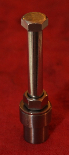
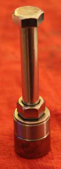
Picture 1: Side View W/Needle Bearing. ( Click on image to enlarge. )

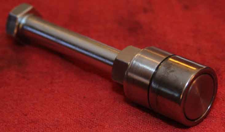
Picture 2: End View W/Needle Bearing. ( Click on image to enlarge. )